Albin 27 Bowsprit & Swim Platform
Bowsprit
One of the reasons I love the A27 is the anchor paltform/bowsprit. But to me a proper vessal has robust ground tackle and an overbuilt bowsprit. I think I'm going to transition to no (or really limited) exterior wood. Whether I keep the wood anchor platform or not, it needs a little support underneath, because you should be able to stand on it and jump off it. I thought about adding a plate underneath. Then I thought about getting rid of the wood altogether. I am of the opinion that you should be able to stand on your bow pulpit and jump off it.
I think I can get a piece of stainless or aluminum the same size as the existing platform (1/4"x15x30"?) Then have someone weld two lengthwise stringers on the bottom of plate to strengthen the plate. On top of the plate I would attach thin strips of hdpe in a tread pattern. The anchor platfrom would be bulletproof then. This is similar to a anchor platfrom design I used my Alber 30 sailboat, except that one was made of mahogany. It looked beautiful, no doubt, but was alot of upkeep.
I think I can get a piece of stainless or aluminum the same size as the existing platform (1/4"x15x30"?) Then have someone weld two lengthwise stringers on the bottom of plate to strengthen the plate. On top of the plate I would attach thin strips of hdpe in a tread pattern. The anchor platfrom would be bulletproof then. This is similar to a anchor platfrom design I used my Alber 30 sailboat, except that one was made of mahogany. It looked beautiful, no doubt, but was alot of upkeep.
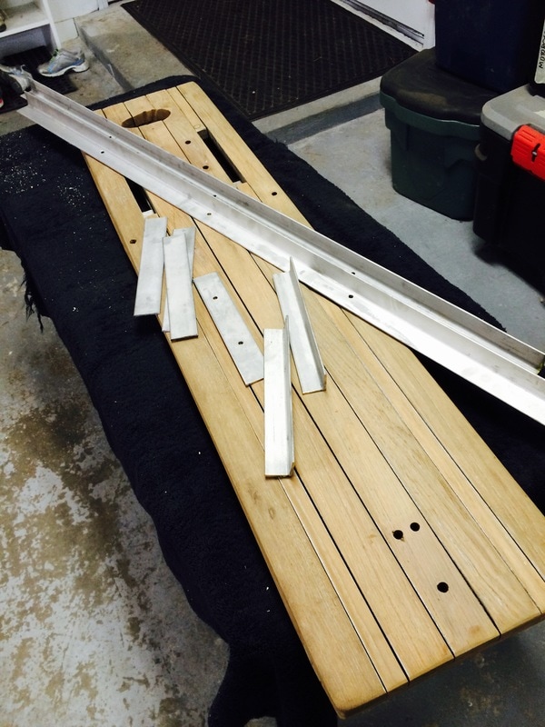
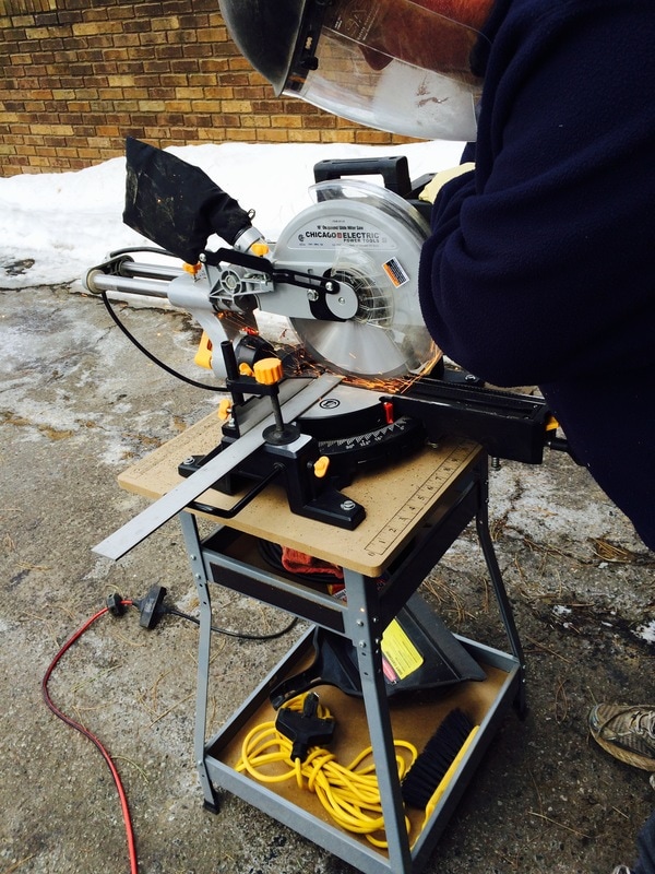
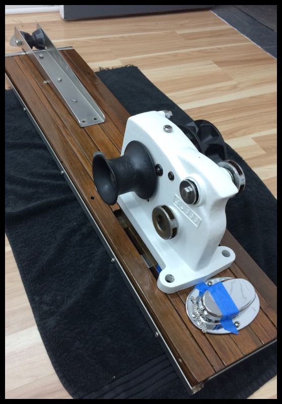
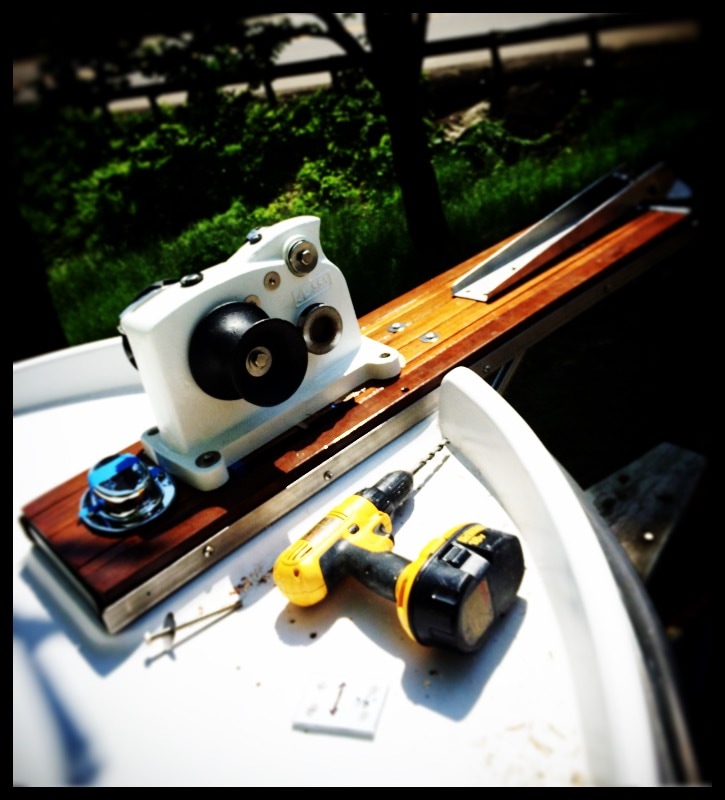
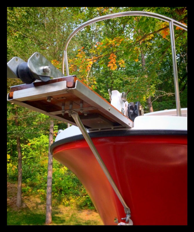
So after careful review, I decided my wood was in very good condition and it seemed a shame(not to mention more work) to swap everything out to hdpe or stainless. I decided to keep my teak bowsprit and reinforce it with a stainless steel frame. I will probably regret this, as this means I'll be keeping all my teak handrails, hatches, etc. But I guess a little bit of woodwork is a good thing. I purchased about $100 worth of 316 stainless steel angle bar and flat bar, 1/8"x1.5" online. I plan to cut the pieces myself and then have a welder put it together. The stainless frame will bolt to the teak bowsprit. The seatiger 555 windlass looks nice and I think everything will fit nicely on the box. I plan to put the bollard immediately aft of the bowsprit, on a 1" raised hdpe pad.
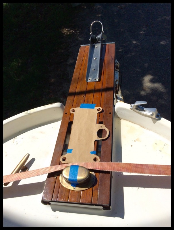
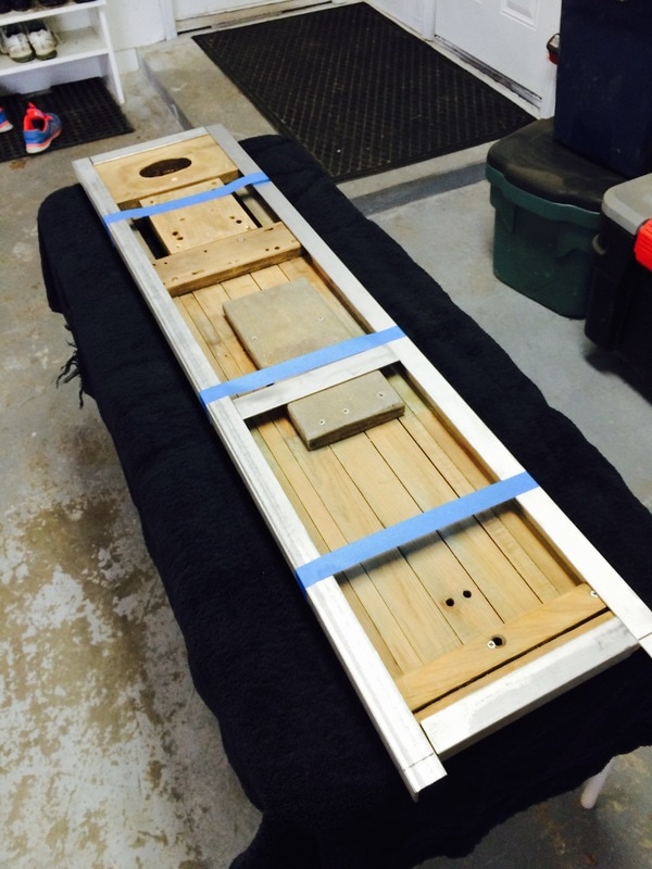
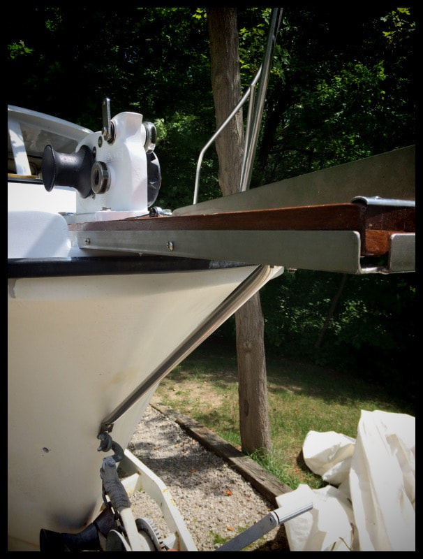
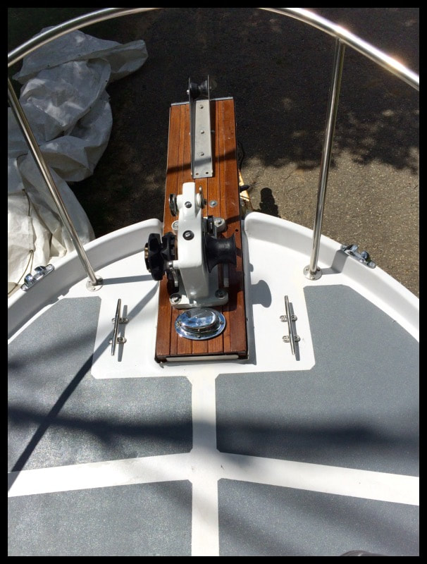
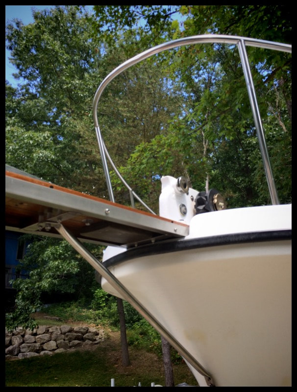
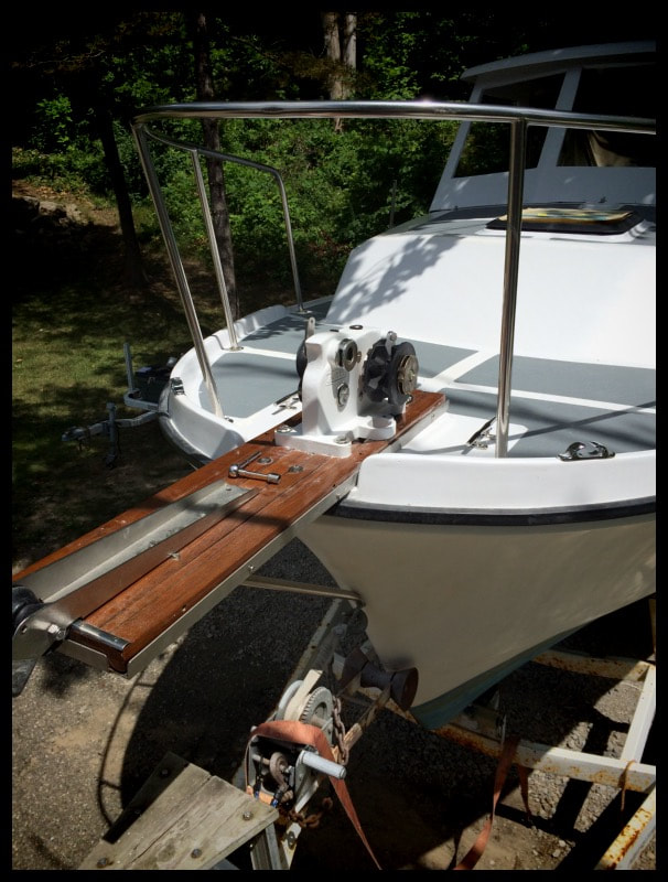
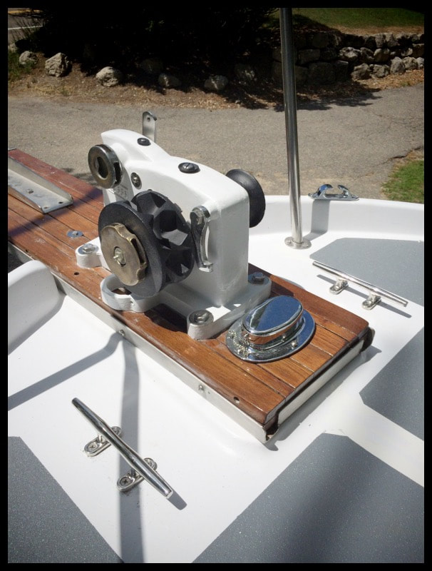
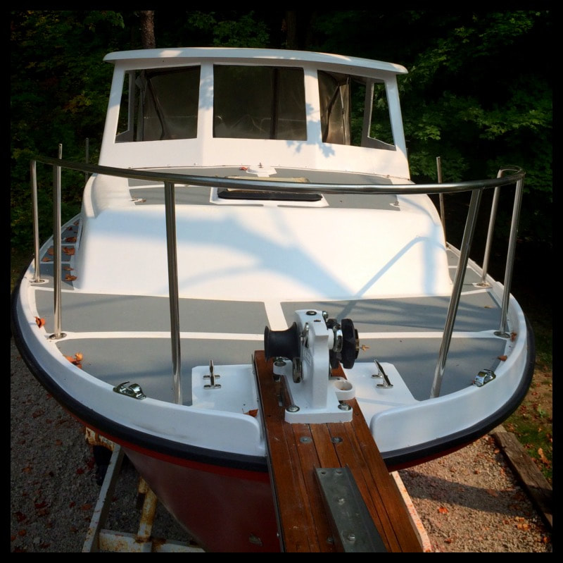
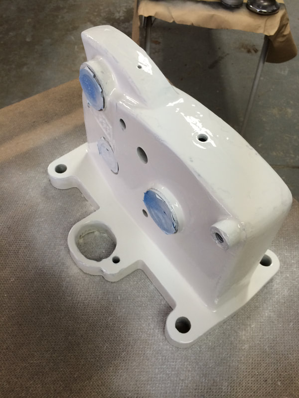
Dry fit of the rebuilt bowsprit/anchor platform. Trying to get an idea where the oversized chocks and cleats will go. My bowsprit has a haws pipe at the aft most end which dumps chain/rode into the anchor locker. The bulkhead is just inches behind where the aft end of the bowsprit ends. Thinking of placing a cleat on a raised 3/4" standoff block on each side of the bowsprit. I can back the deck easily in the anchor locker with coosa board. This would keep the lines at the correct angles for the chocks. I like the center post bollard that came with the boat but there's no way to mount it with the Seatiger 555 windlass and the haws pipe as is.
Dry fit of the rebuilt bowsprit/anchor platform. Trying to get an idea where the oversized chocks and cleats will go. My bowsprit has a haws pipe at the aft most end which dumps chain/rode into the anchor locker. The bulkhead is just inches behind where the aft end of the bowsprit ends. Thinking of placing a cleat on a raised 3/4" standoff block on each side of the bowsprit. I can back the deck easily in the anchor locker with coosa board. This would keep the lines at the correct angles for the chocks. I like the center post bollard that came with the boat but there's no way to mount it with the Seatiger 555 windlass and the haws pipe as is.
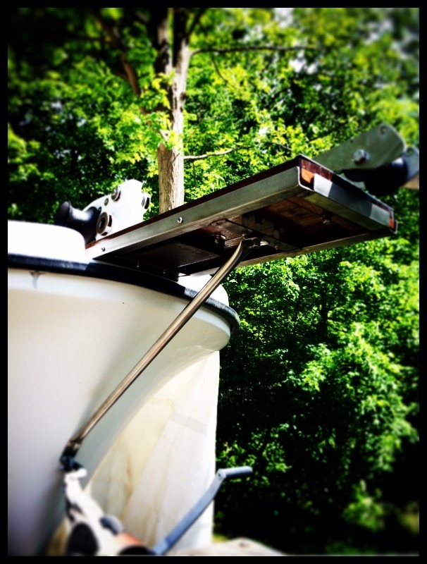
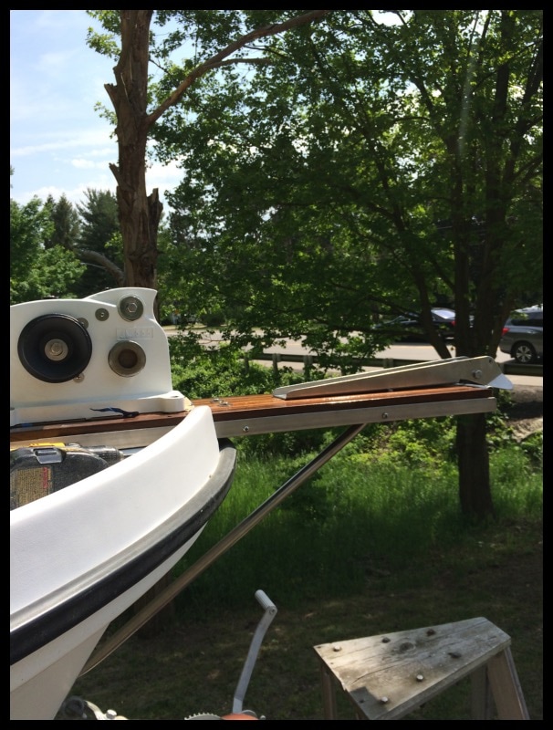

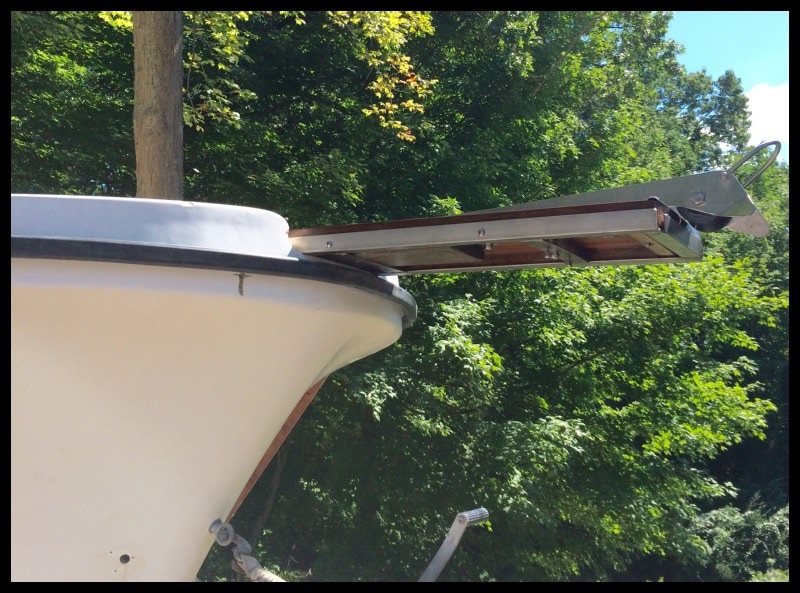
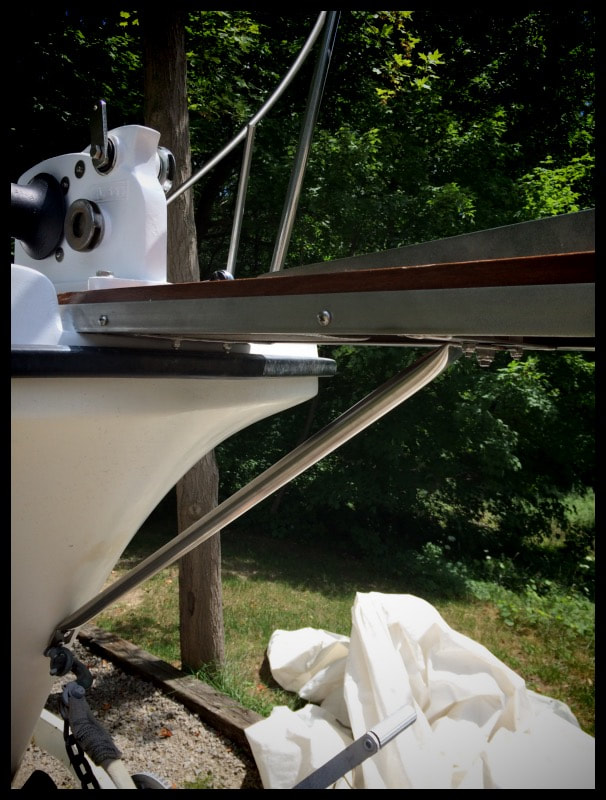
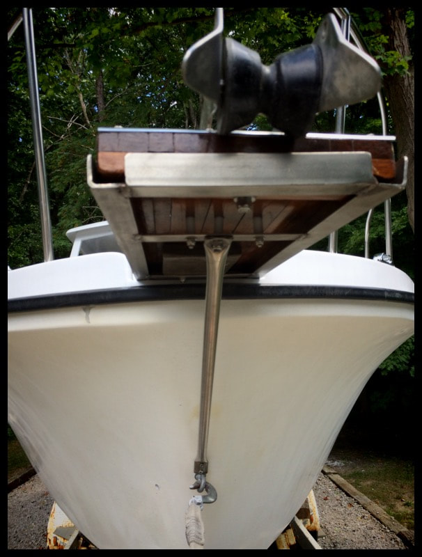
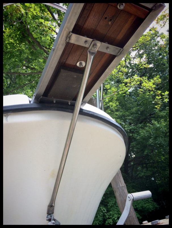
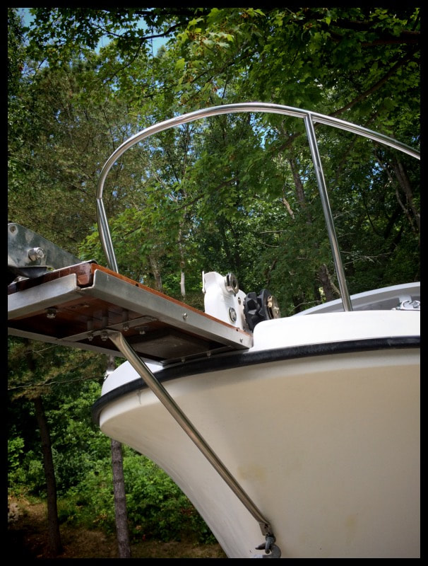
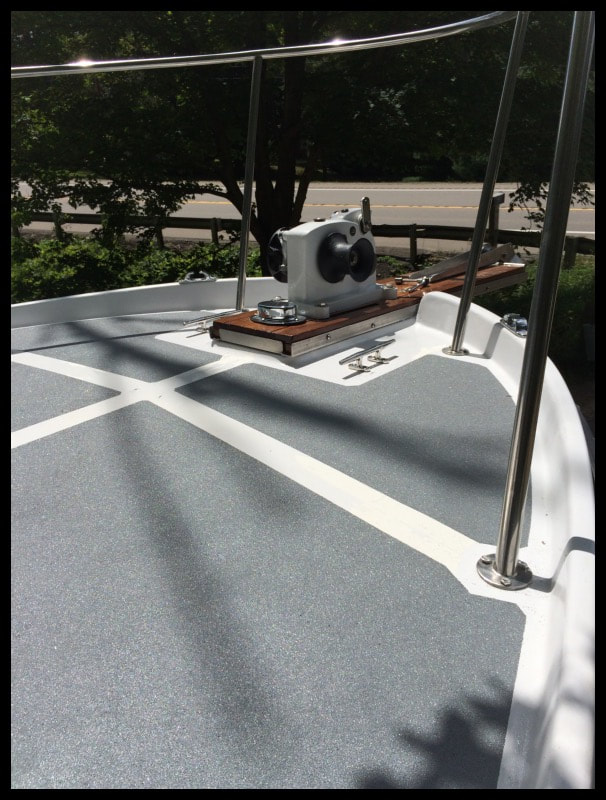
Finally, after a lot of work and small projects, the fore deck comes together. The SeaTiger manual windlass is now mounted through the bowsprit, and then the deck, via 1/2" stainless bolts. The bowsprit has been framed in a stainless steel framework to give it added strength, which now allows it to be further supported by the a support strut attached to the bow. By moving the forward deck cleats and repositioning the bow chocks, the fore deck has taken on a proper organized layout.


Deck Fittings & Stanchions
Fall 2015: I have a full set of stanchions and life lines already installed. Probably embed that too. Someone went through some expense and effort. Three stanchions each side, plus double life lines, and elbow supports & line hooks for the stanchions mid ship for boarding. Brilliant idea. Too bad they didn't through bolt with backing plates. They just fiberglassed everything below! What is with this idea of fiberglassing backings for deck fittings. Insane! This weekend I start grinding everything off. Deck hardware is coming off. Under the stanchions i found plywood blocks very small. The stanchions are one piece pipe with bases. Very nicely done. All welded and capped.some have lateral suports that bolt on. I havent been able to find anything store bought thats similar so they must have spent a pretty penny. They're really very nice. Stanchions used sloted bolts.
On the Albin 27, the fore and aft pulpits are mounted through the deck. There is an aluminum plate glassed into deck at each base. Then nuts then the whole thing was glassed over. Pulpits used hex bolts. Deck cleats use panhead bolts and are backed by two 1" stainless flat pieces. Also glassed over. I made it through the aft part of the boat. I have four bases to go on bow pulpit then all the deck fittings will be off the boat. I can cover the boat for winter and switch to wood & plastic work. I'm thinking of changing out the all the wood to hdpe (king starboard) and the anchor platform to stainless. Not sure what to do with the swim platform. Its covered in deck renew. Yes, that horrible stuff that encases your deck and cracks over time. Not a good scene.
On the Albin 27, the fore and aft pulpits are mounted through the deck. There is an aluminum plate glassed into deck at each base. Then nuts then the whole thing was glassed over. Pulpits used hex bolts. Deck cleats use panhead bolts and are backed by two 1" stainless flat pieces. Also glassed over. I made it through the aft part of the boat. I have four bases to go on bow pulpit then all the deck fittings will be off the boat. I can cover the boat for winter and switch to wood & plastic work. I'm thinking of changing out the all the wood to hdpe (king starboard) and the anchor platform to stainless. Not sure what to do with the swim platform. Its covered in deck renew. Yes, that horrible stuff that encases your deck and cracks over time. Not a good scene.
After a long season, I got the deck hardware finally removed. After much grinding below decks, the aft and bow pulpits came right off. Everything stowed for winter. I will be working on wood trim, bowsprit, mast, and other details. I'm almost positive I'm going to take the wood window trim, interior and exterior and make black hdpe trim out of 1/4" thick stock. And probably the hand-holds, deck blocks etc. The wood is nice but an invitation to extra work down the road. Next summer, I will seal all the leaks, repair the ports, fiberglass the interior for the new head, build the mast step, power-wash & clean interior hull and possibly spray coat interior. To be continued....
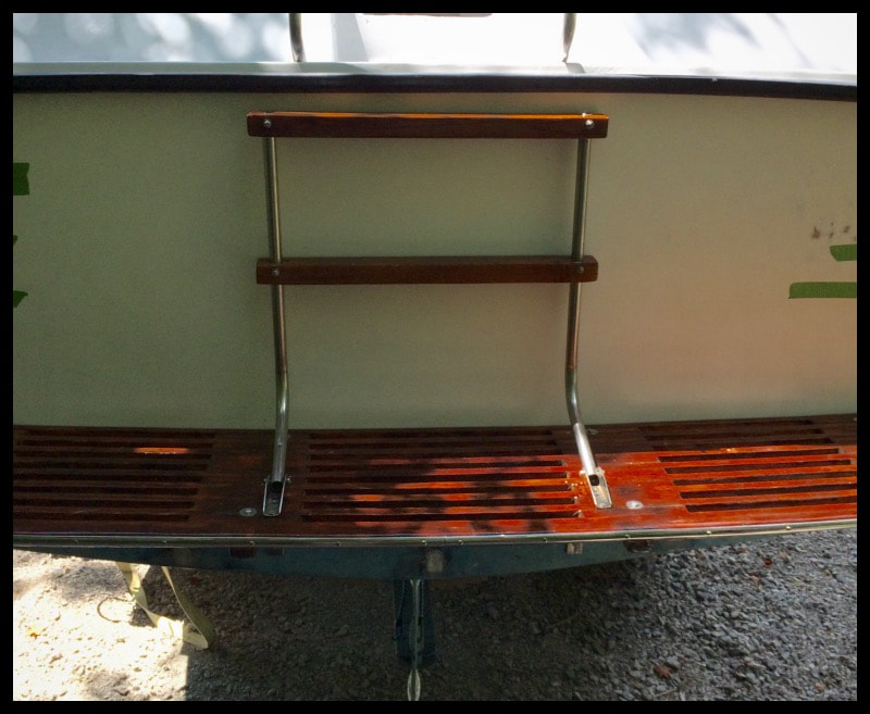
Swim Platform
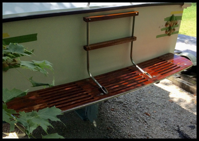
While I wait for more materials for the head project, I started looking at my swim platform. The old platform was deemed unserviceable because it had been coated with Deck Restore by the previous owner (PO). The new platform is a Craigslist special, formerly off a big wooden Chriscraft. Its in rough shape; I found behind a row house in Detroit. But the price was right even if it had flaking varnish. The teak seems ok but needs a lot of cleanup and sanding. I salvaged Salvage all the stainless hardware for re-use. Some of the holes will probably line up. First, I scraped & sand with a belt sander set to 60 grit.
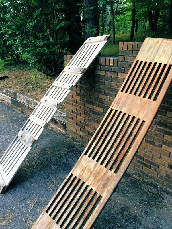
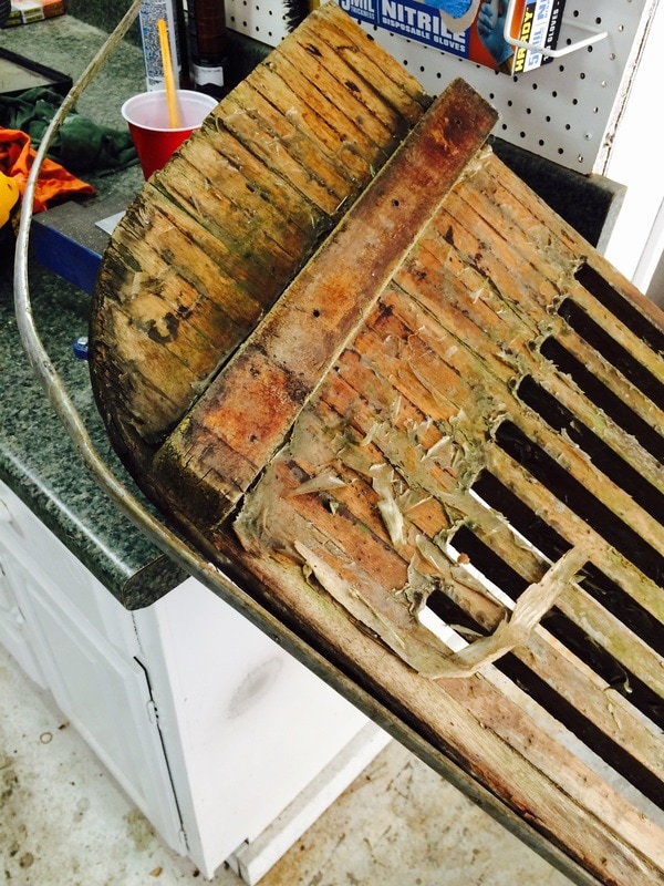
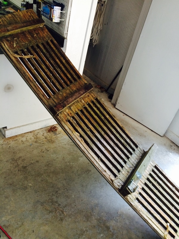
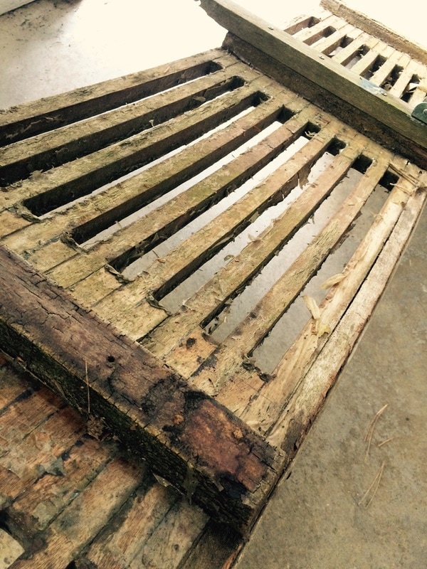
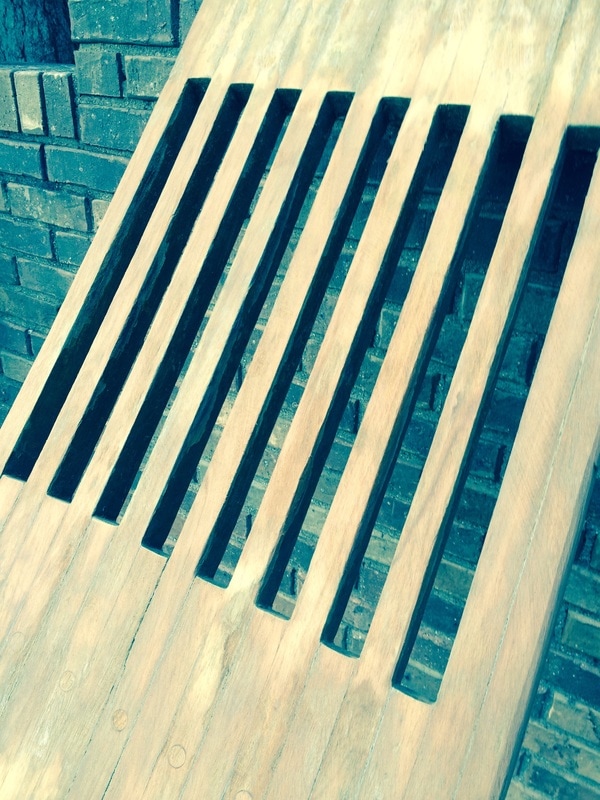
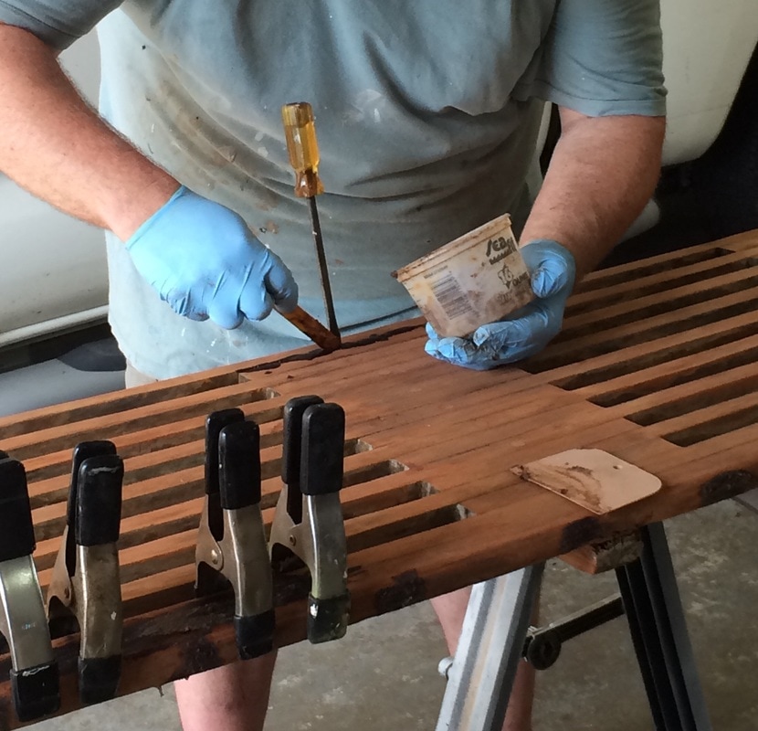
Initial sanding was done in a weekend. I noticed several places where the original teak had split along a joint so I mixed up some epoxy with teak dust (leftover from sanding) and filled in the joints. Dry fit to the boat was excellent. This platform follows the curve of transom perfectly. I will fill old holes and drill new ones with backing plates. My platform mounts via four L brackets and four struts.

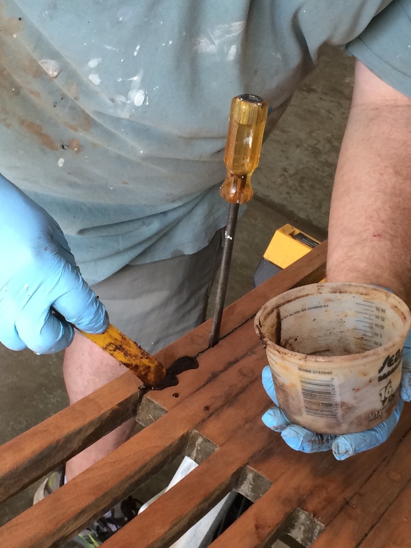
For my brightwork I use Cetol Sikens exclusively. Over the years I've found Cetol is the easiest to apply, easiest to repair, and it lasts the longest between touch ups. The down side is the color for many people. On really clean wood and teak it's not the best looking, I concede. But on 39 year old wood that's been abused, it's a great solution. And some have complained that Cetol peels over time leaving sharp slivers--but I've never had this happen in all my years of using it. I have seen this with epoxy ( not UV resistant) and with some varnish.
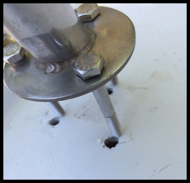
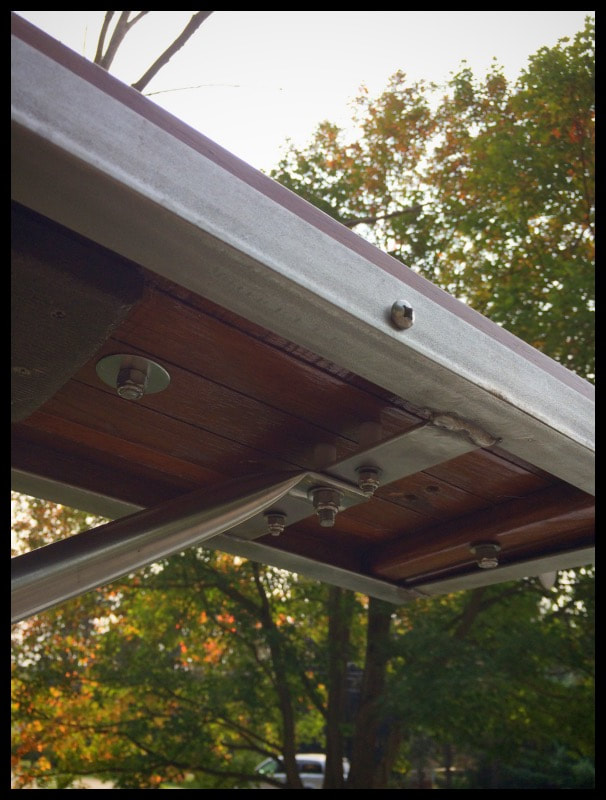
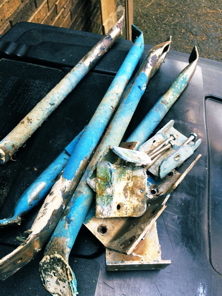
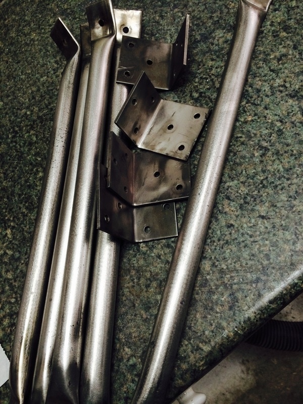
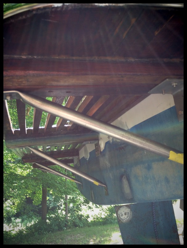
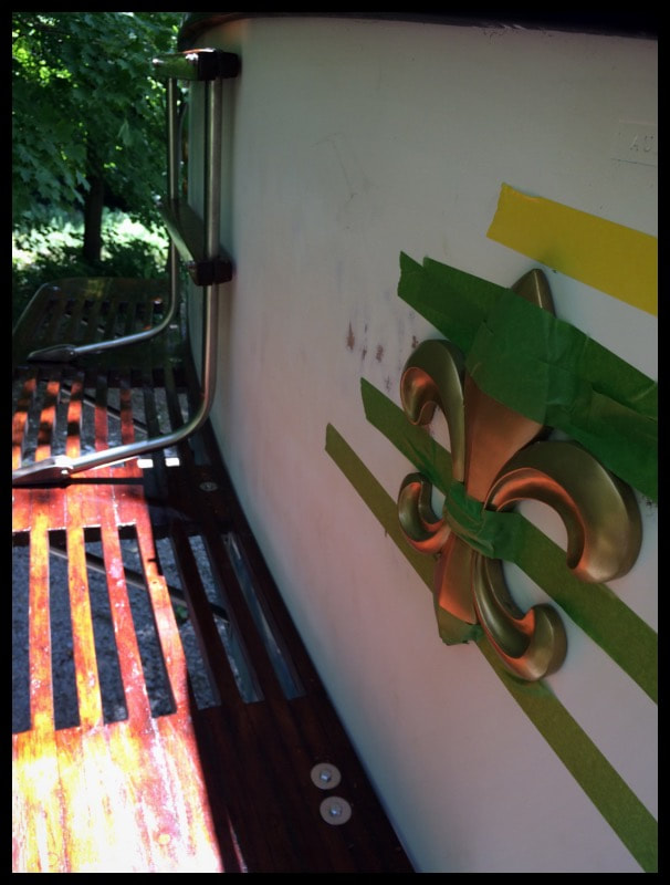
To mount the platform I'm using the same set up as the original A27. Which is top brackets and bottom struts. Across the top of the platform on the underside are (4) 3x3" brackets which are basically stainless angle flat stock. Two bolts to platform, three to hull. Then there are 4 struts which are 1" stainless pipe that bolt to the aft edge of the platform underside and go 45 degrees to the bottom of the hull at waterline. This was the original A27 setup. Inside the hull I used very large 3/4" coosa board backing blocks for thru bolting. With the new platform I had to reposition the brackets and struts to match the new platform. I located some scrap half round stainless to add to the edge of the swim platform. If you start from the center you can work your way around the corner radius slowly and avoid the metal buckling from being bent.
To mount the platform I'm using the same set up as the original A27. Which is top brackets and bottom struts. Across the top of the platform on the underside are (4) 3x3" brackets which are basically stainless angle flat stock. Two bolts to platform, three to hull. Then there are 4 struts which are 1" stainless pipe that bolt to the aft edge of the platform underside and go 45 degrees to the bottom of the hull at waterline. This was the original A27 setup. Inside the hull I used very large 3/4" coosa board backing blocks for thru bolting. With the new platform I had to reposition the brackets and struts to match the new platform. I located some scrap half round stainless to add to the edge of the swim platform. If you start from the center you can work your way around the corner radius slowly and avoid the metal buckling from being bent.
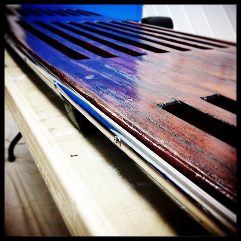
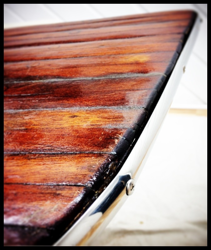
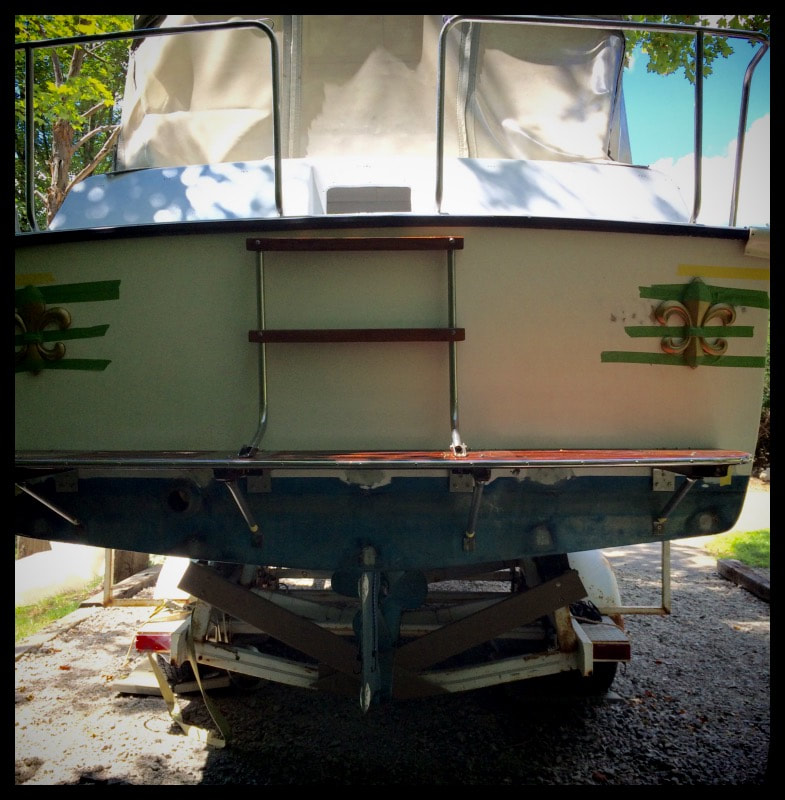
The replacement swim platform fits the boat well. Its about 2" less wide, but 2" deeper than the original. I was able to reuse virtually all the original stainless hardware, except for the stainless brackets that attach the platform to the transom. The originals had the mount holes in the wrong place, and frankly they didn't appear that robust. So I bought about a foot of 2" stainless angle beam and cut my own brackets, drilling the holes exactly where I wanted them. The result is a superior mounting system that makes the platform totally solid. The original boarding ladder fits perfectly and doubles as steps leading onto the back deck of the boat. Photos of the dryfit before the hull gets painted.


Sea Tiger 555 Manual Windlass
|
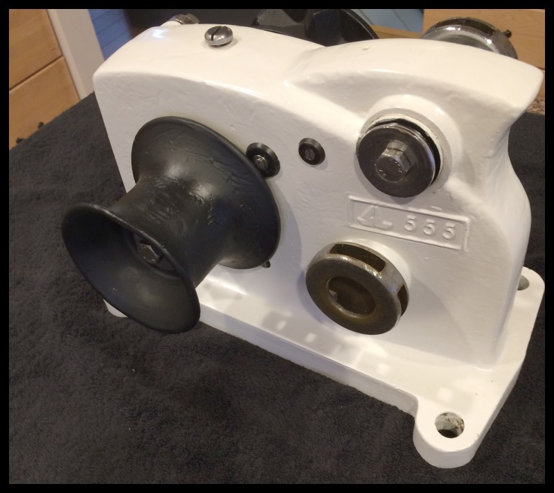
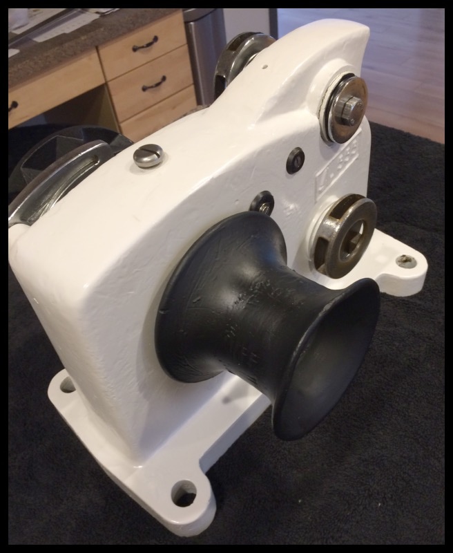
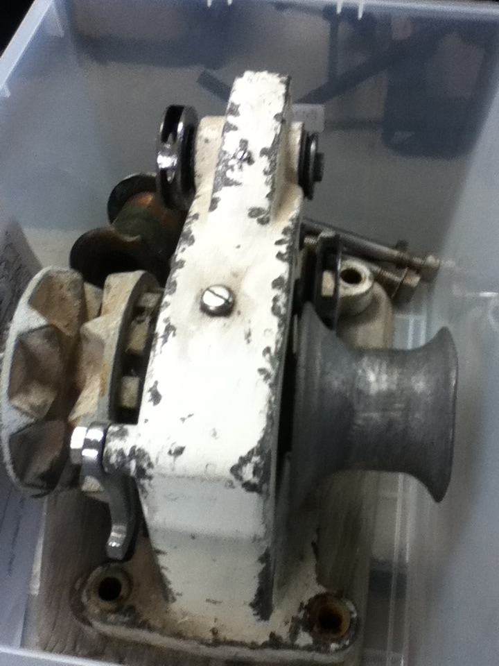
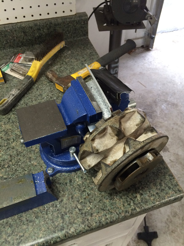
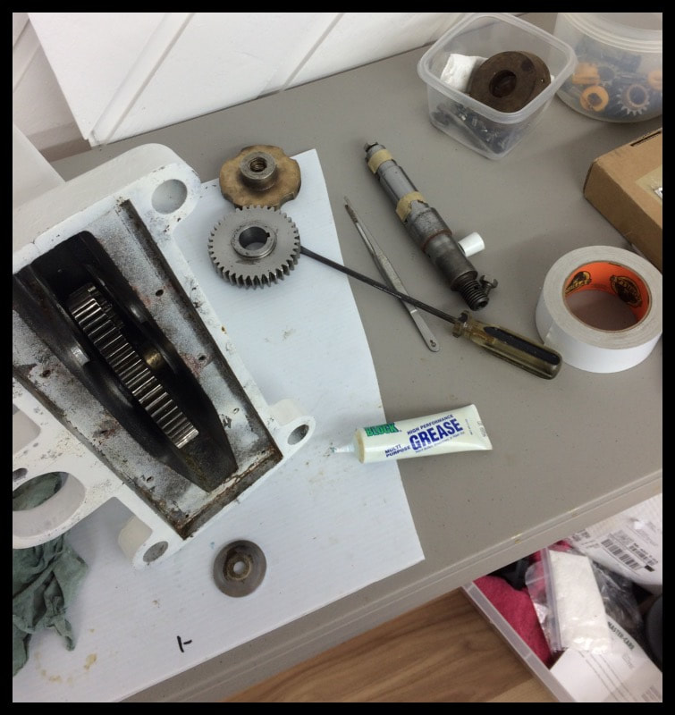
This project has been cluttering up my shop for about 2 years. I was dreading putting it back together, but turns out it's relatively simple. This thing is impressively built. If you can locate one of these it's worth the effort to rebuild it since they're no longer being made. Today there's only 1one or two manual windlasses available and they're not built as well as the venerable SeaTiger 555 manual anchor windlass.
Took eight tries putting it together, but I'm a little slow on figuring things out mechanically. Lots of heavy gears and they go together a specific way.Reassembled Seatiger 555. This thing was basically free. Cost about $100 for some spare parts from Scotland. That bow roller on there now is at least 1-2 sizes up from the original bow roller. |
Step 1: Preparation
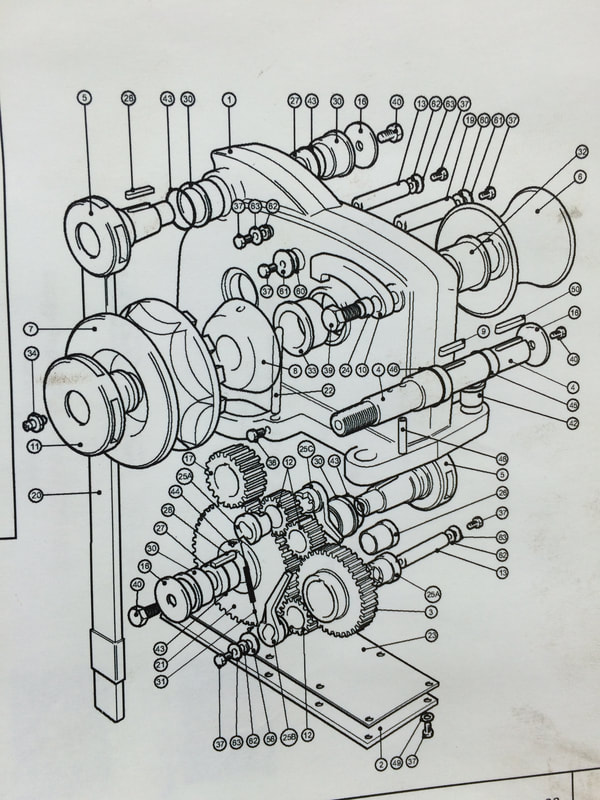
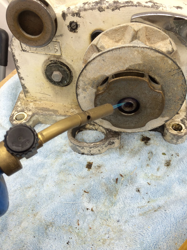
Clean the exterior of the unit using Simple Green in a wash tub or deep sink. You will need to refer to the parts diagram to identify parts by number. For parts that appear seized or rusted, apply penetrating oil and alternating heat over 1-3 days. You will need the following tools:
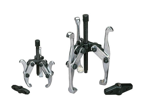
8” three leg puller from Harbor Freight ($14)
Crescent and Box Wrenches (Sizes 10mm, 12mm, 20mm)
Rubber or wooden mallet
Flat head screwdriver
Long nose pliars
Windlass handle or pry bar
Clean the exterior of the unit using Simple Green in a wash tub or deep sink. You will need to refer to the parts diagram to identify parts by number. For parts that appear seized or rusted, apply penetrating oil and alternating heat over 1-3 days. You will need the following tools:
8” three leg puller from Harbor Freight ($14)
Crescent and Box Wrenches (Sizes 10mm, 12mm, 20mm)
Rubber or wooden mallet
Flat head screwdriver
Long nose pliars
Windlass handle or pry bar
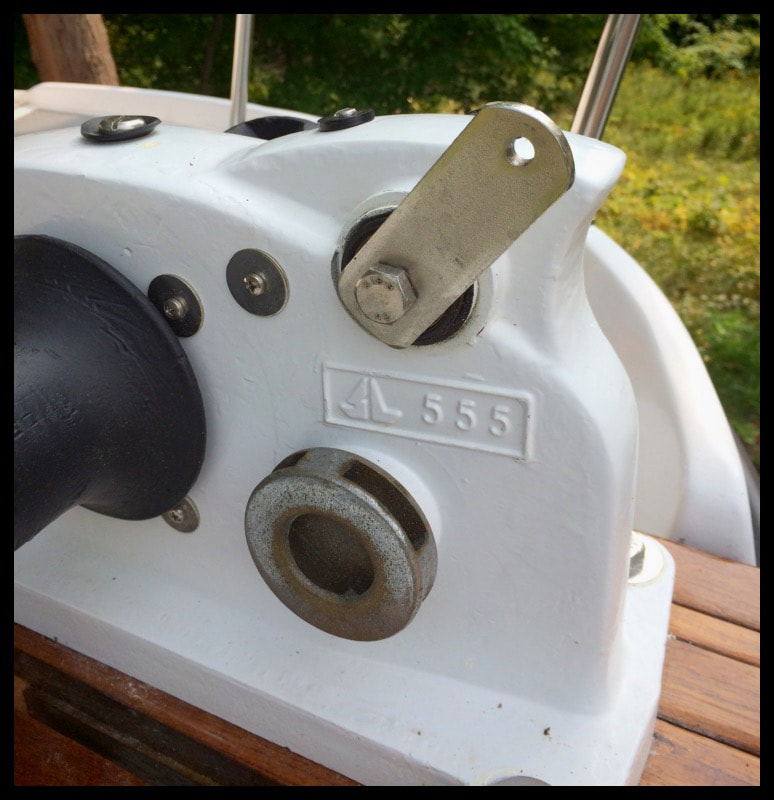
Step 2: Determine Version of SeaTiger 555 Windlass
**Be advised that there were two versions of the Sea Tiger 555.**
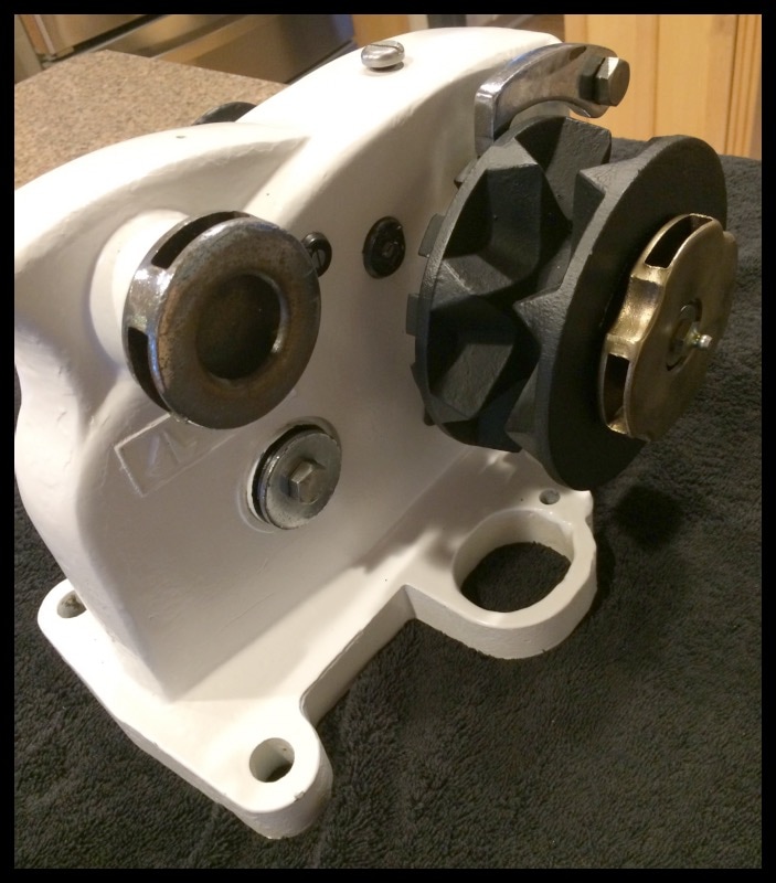
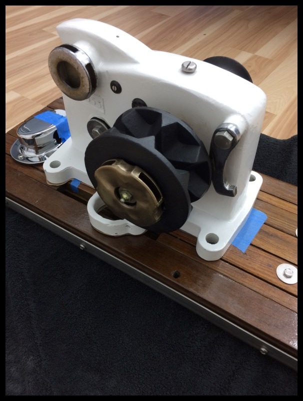
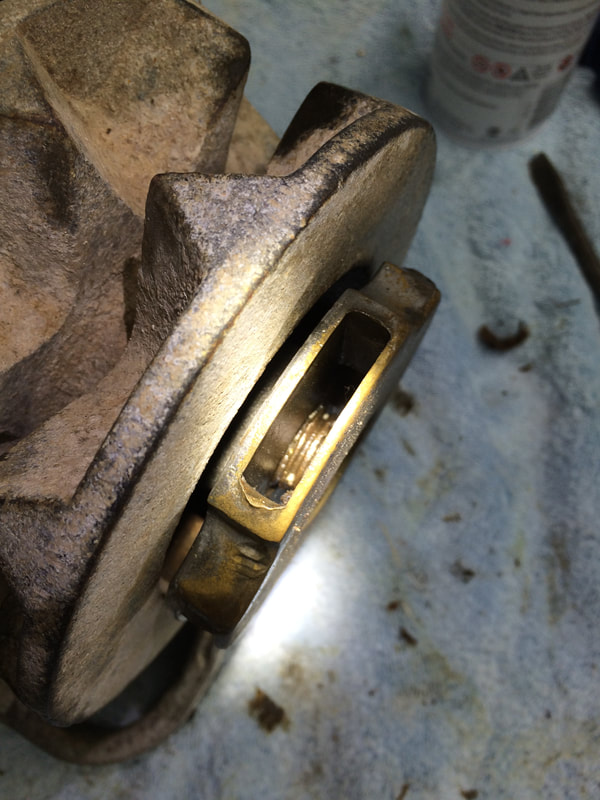
One version was manufactured prior to approximately 1985. The other version is considered the new version, manufactured approximately 1985. You can tell the difference between the two models by looking closely at the Operating Spindle Assembly (part#5). If you see a an o-ring or seal behind where you insert the handle, most likely you have an older model. Older units had an exterior seal, called a “heart seal” (no longer made). Approximate replacements for the heart seals would be X or V shaped o rings bought from McMaster Carr. New model units had grooves cut into the main shaft and Operating Spindle Assembly where an o-ring would set against the bushes (part#30).
**Be advised that there were two versions of the Sea Tiger 555.**
One version was manufactured prior to approximately 1985. The other version is considered the new version, manufactured approximately 1985. You can tell the difference between the two models by looking closely at the Operating Spindle Assembly (part#5). If you see a an o-ring or seal behind where you insert the handle, most likely you have an older model. Older units had an exterior seal, called a “heart seal” (no longer made). Approximate replacements for the heart seals would be X or V shaped o rings bought from McMaster Carr. New model units had grooves cut into the main shaft and Operating Spindle Assembly where an o-ring would set against the bushes (part#30).


Step 3: Disassemble
- Remove the bolt (part#38) that holds the chain stripper (part #22)in place. If you can’t get the bolt out, you can drill it out. The purpose is to be able to remove the chain stripper so you can later remove the gipsy and main shaft assembly (part#4). If the bolt strips out and you have to drill it out, you will have re-drill and tap a hole from a different angle or side to hold the chain stripper in place.
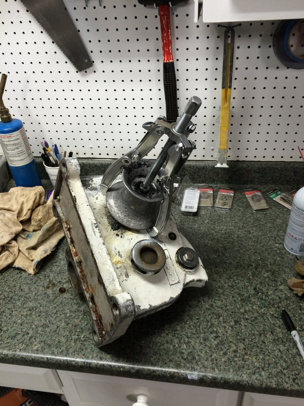
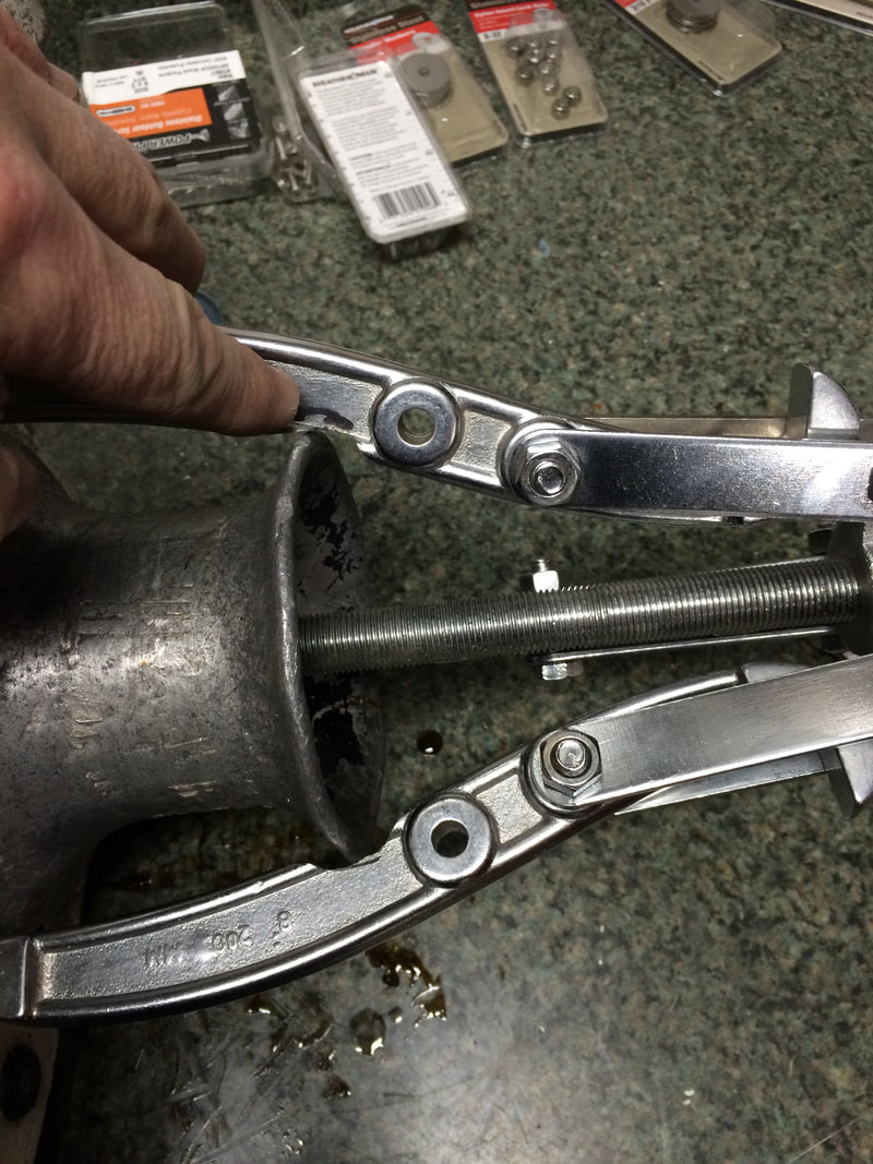
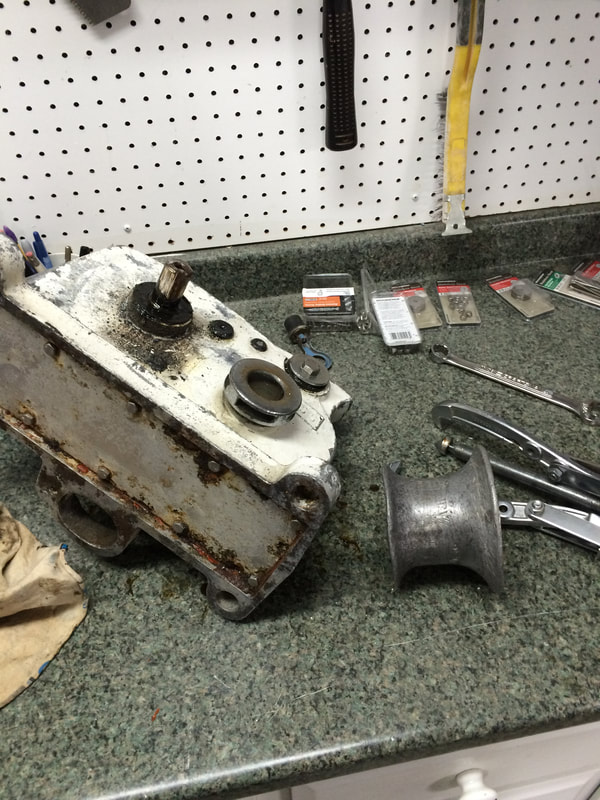
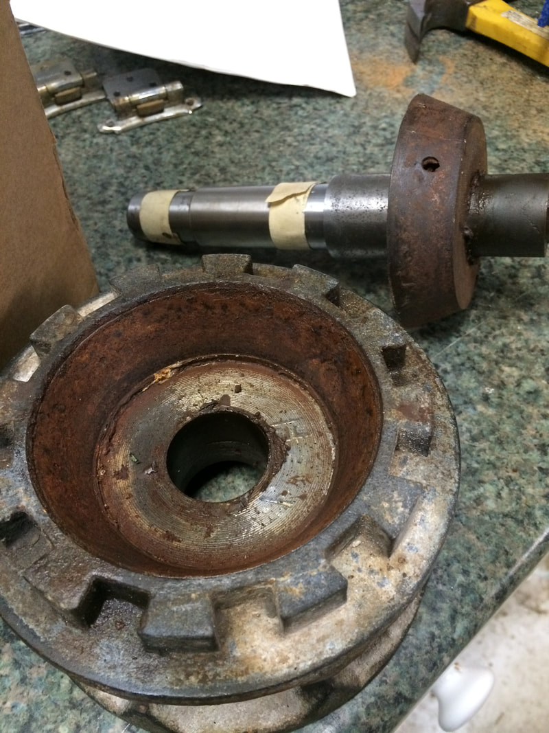
- Remove the gipsy (part#7) and the drum (part#6). The gipsy is secured by the clutch nut (part#11). The drum is secured with a bolt (part#40) and washer (part#16); and there is a key (part#50) into the shaft. Remove the grease nipple (part#34) and the clutch nut (part#11). If you cannot remove the gipsy or drum by hand, you may need to use a 8” three leg puller to remove the drum first and pull the shaft out the other side with the clutch nut still attached. Note: The 8”three leg puller from Harbor Freight will almost fit around the drum, but you may need to slightly grind the legs so it fits snuggly. When using the puller, be careful not to damage the aluminum drum or drum edges. You can use a piece of wood dowel to tap out the shaft once you have either the drum or clutch nut removed. Inside the gipsy there is a clutch cone (part#6) which appear molded to the gipsy but will come apart if you tap against the shaft and gipsy.The gipsy is secured by the clutch nut (paty#11) and the drum is secured with bolt (pary #40) and washer (part #16) and is keyed onto the shaft with key (part #50).
- Then remove the bottom cover (part #2) and gasket (part #23) by removing bolts (part #37) and washers (part #49). If the bolts are corroded, replace with stainless. Bolts are metric size and thread.
- I used a mallet or with a small dowel drive out the main shaft (part #4)
- Take out the ratchet shaft bolts (part #37), washers (parts# 63) and seals (part #62) from the lower most shaft (part #13) in the diagram. Tap out the ratchet shaft (part #13) with a metal bar or pipe, it should be a larger diameter than the bolt hole so it doesn’t damage the threads. Next remove all washers (part #58) on either side of the gear.


6. Remove bolts ( part #37), washers (part #61) and seals (part #60) from idler shaft (part #19).
7. Remove the ratchet shaft bolts (part #37), washers (part #63) and seals (part #62) from the upper ratchet shaft (13) in the diagram and tap out as described above.
8. Remove ratchet assembly (parts #25A,25B,25C) and 2 gears (parts #12) together with springs (parts #31) and screws (parts #44)
9. Remove bolts (parts #40), washers (parts #16) and bushes (parts #27) from both operating spindles (parts #5). It can be difficult to separate the spindles from the shaft because the the shaft us tapered. A manual or hydraulic press may be necessary to separate. ***Be careful not to crack main case***
10. Remove all gears. Apply light sand paper or bronze wool to all surfaces if surface corrosion. Check bushings for excessive wear. Replace O rings and seals. Apply grease via grease nipple and by packing inside case before replacing bottom cover.

Step 3: Reassemble
- Insert gear (part #17), insert operating spindle (part #5), insert key (part #21) with gear, insert bushing (part #27) and assemble with washer (part #16) and bolt (part #40).
- Insert gear (part #21), insert operating spindle (part #5) insert key (part #21) with gear, insert bushing (part #27) and assemble with washer (part #16) and bolt (part #40).
- Insert ratchet set (parts #25A x 2 , 25B, 25C) into gears (part #12), insert gear with short arm (part #25C) inside the main case first and roll back the gear into position. Install the upper ratchet shaft (part #13) with new seals (part #62), washers (part #63) and bolts ( part #37).
- Pull back the “free” ratchet and roll the idler gear (part #12) behind the ratchet arm (part #25B). Install the idler shaft (part #19) with seals (part #60), washers (part #61) and bolts (part #37). Install washers (part #58) either side of gear and install lower ratchet shaft (part #13) with seals (part #62), washers (part #63) and bolts (part #37). Install main shaft aligning the key. Apply grease to the inside of the unit before replacing bottom cover. Assemble base gasket and bottom cover with bolts (parts #37) and washers (parts #49).